
Also, the I2C master can use both the 7 and 10-bit addresses on the same bus.Īdditionally, there are some breakout boards that allow communication with multiple slave devices using a common address. In 10-bit addressing, 1008 slave devices can be connected to the bus. In 7-bit addressing, 112 slave devices can be connected to the bus. The in-band addressing can be a 7 or 10-bit. Many slave devices have a configurable I2C address. The I2C addresses of the various slave devices are decided by NXP. The master device uses in-band addressing to access the communication with the slave devices. This successfully avoids any bus contention.Įach I2C slave that’s connected to a bus must have a unique address. The wires are pulled HIGH by default, using the pull-up resistors and the I2C drivers are open-drain (meaning, they can only pull the line LOW). This means any number of master devices can be connected to the I2C bus, but only one master can control the bus at one time. Since there is just one data line, only the half-duplex communication with a single slave device is possible at one time.

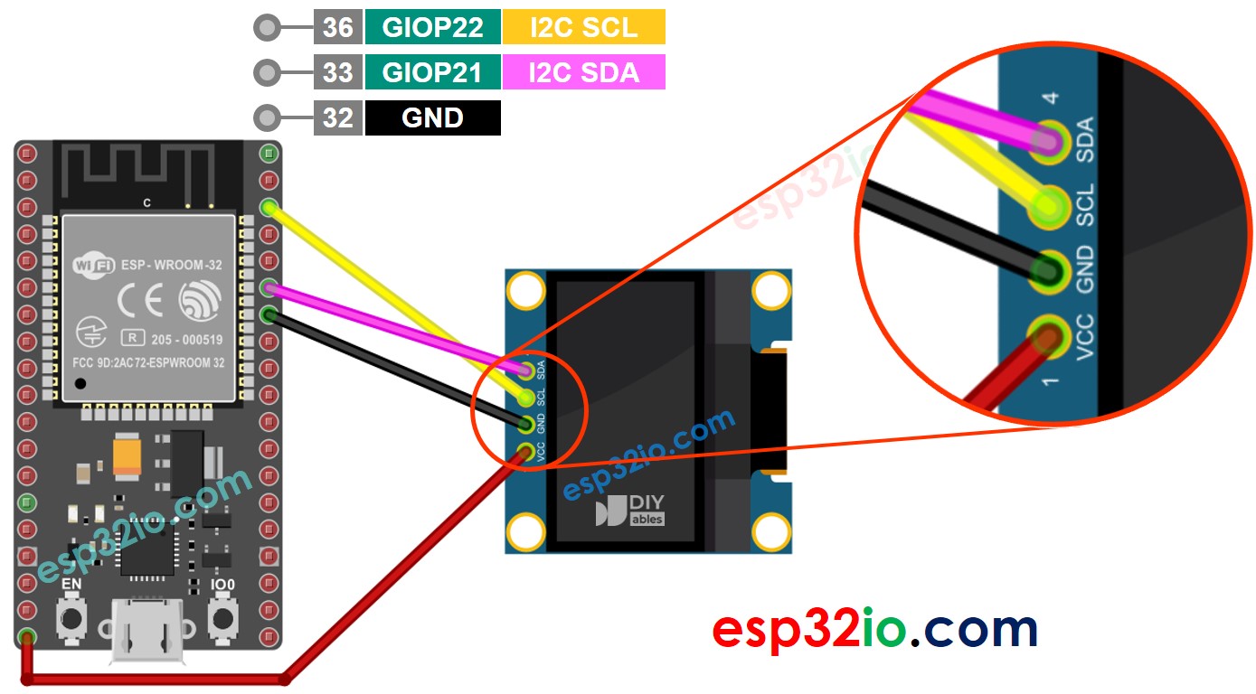
Controlling the read/write operations over the bus.Selecting a slave device for communication.The master device is responsible for synchronizing data transfers by: The I2C is a master-slave type bus and there should be at least one master device to control the two-wire bus. On a two-wire bus, hundreds of master and slave devices can communicate serial data using the I2C protocol. The I2C bus has only two wires: one is a data line (SDA) and one is a clock line (SCL).

The I2C, or TWI, is a synchronous master-slave serial communication protocol originally developed by Philips Semiconductors (which is now NXP).

Now, in this tutorial, we’ll learn about synchronous serial communication in Arduino using the inter-integrated circuit (I2C) bus. SPI bus is used for full-duplex synchronous serial communication with multiple devices. The I2C or two-wire interface (TWI) is used for half-duplex synchronous serial communication with multiple devices in a master-slave fashion. UART is useful for full-duplex serial communication with a single device over two wires. The universal asynchronous receiver/transmitter (UART), I2C, and SPI are the most commonly used serial interfaces in embedded systems. In previous tutorials, we’ve covered serial communication using the UART and software serial in Arduino.


 0 kommentar(er)
